Minggu lalu sudah dibahas mengenai pengertian modulasi. Untuk kali ini, terdapat beberapa contoh perangkat dan spesifikasinya yang berhubungan dengan jenis-jenis modulasi tersebut.
1. Modulasi FM
Untuk perangkat pada modulasi fm yang sering kita dengar tentunya yaitu pemancar radio itu sendiri.
TF(S)- 500 FM Stereo Transmitter
Fitur:
1. Pemancar selalu stabil.
2. 16*500W wide band amplifier cards, dilengkapi dengan transistor Philips BLF177, assure the highest menjamin redudansi tertinggi. Tidak ada pentesuaian khusus untuk operasi daya tinggi pada frekuensi 87 ~ 108 MHz.
3. Radiasi dengan harmonisasi super (<-70dB, typical –75dB). 3 low pass filters yang dapat mengurangi pada gangguan penerimaan.
4. Amplifier seudah dirancang dalam satu blok. 4*500W dibuat dalam satu blok dan masuk dalam rak standar 19”. Pemelharaan dapat dilakukan oleh sedikit tenaga ahli.
5. Fungsi dengan perlindungan penuh, seperti kelebihan temperatur, kelebihan tegangan, kelebihan arus, VSWR dan lain-lain. Pemancar akan terus bekerja pada setengah daya input .
7. Panel depan akan menampilkan daya output, daya pancar, tegangan dan arus dari power supply.
Spesifikasi utama:
Rentang Frekuensi : 87 ~ 108 MHz
Daya output : 5KW
Impedansi output : 50 ohm/co-xial
Jenis konektor output : 1 5/8 Flange
Radiasi bayangan : -70dB
Impedansi audio input : 600 ohm/balance
Level audio input : 0 dBm
Deviasi frekuensi : 75KHz at 100% modulation
Distorsi audio : < 0.2% ( 40Hz ~ 15KHz)
Respon frekuensi : <±0.3 dB ( 40Hz ~ 15KHz)
Penekanan awal : 0 us/50us/75us
S/N rasio : > 70 dB
Pemisahan : > 50 dB ( typical)
Frekunsi stabil : < ±500Hz ( -10 °C ~ + 45 °C)
Konsumsi Tegangan : 11KVA
Dimensi : 584 (Lebar)*2000( Tinggi)*800(Panjang)
Berat : 400 KG
2. Modulasi AM
Sama halnya perangkat dengan modulasi FM, pada modulasi AM juga perangkat yang sering dijumpai yaitu pemancar AM. Contoh spesifikasinya yaitu :
TRANSMITTER AM-30P
Spesifikasi pemancar AM
Stabilitas pemancar : +/-0.001%, -4 to +144F (-20C to +50C) w/105-128VAC Line
Daya output RF : 2-30w(Am-30P), 6-60w (AM-60P), 25-100w (AM-100P)
Impedansi output RF : 50 OHM Unbalanced SO-239 Connector
Kontrol daya RF : Internal Adjustment
Indikator daya RF : Internal Meter
Jenis modulasi : 30A3 Amplitude Modulation
Rentang frekuensi : 520-1710 kHz (crystal controlled)
Harmonisasi RF : >50dB Below Carrier
Pergeseran Carrier: <2%, 95% Modulation
Kontrol Modulasi : Internal Adjustment
Indikator Modulasi : Internal Meter
Power Supply 117VAC, 50/60Hz
Rangkaian Tuning : Internal Fine Adjustment for Improved Supression
Konsumsi Daya : 150w (AM-30P), 250w (AM-60P), 450w (AM-100P)
Mechanical (AM-30P) Outer Dimensions: 12"W x 12"H x 6.5"D
3. FSK- modulasi
Telemetri suhu memberikan kemudahan dalam mengukur suhu jarak jauh, dengan pemantauan dari tempat yang aman dan memungkinkan Telemetri suhu biasanya diterapkan, pemantauan suhu gunung berapi, pemantauan suhu pada peleburan baja, pemantauan cuaca yang tidak memungkinkan manusia untuk melakukan pengukuran secara langsung pada jarak yang dekat. Selain itu sistem telemetri sering digunakan pada program luar angkasa untuk mengukur suhu permukaan suatu planet, sehingga keadaan cuaca pada suatu planet dapat diperkirakan. Pengiriman informasi pada telemetri dapat dilakukan secara wireline maupun wireless. Teknik pengiriman informasi merupakan salah satu yang menentukan kehandalan sistem telemetri apalagi jika pengiriman informasi dilakukan secara wireless. Untuk itu pengolahan awal sinyal dan teknik modulasi yang dipilih akan sangat menentukan kehandalan sistem telemetri tersebut. Teknik modulasi awal dilakukan secara FSK kemudian dilanjutkan modulasi secara FM. Pada penerima hasil pengukuran ditampilkan pada layar monitor PC sehingga dibuat juga program antarmuka untuk keperluan tersebut. Hasil pengujian menunjukkan bahwa sistem ini mampu bekerja pada jarak maksimum 700 meter. Pada pengujian selama 24 jam diperoleh hasil bahwa suhu udara tertinggi adalah 29,27º C dan suhu terendah adalah 24,63º C. Pada pengukuran terdapat kesalahan pada pengkonversian suhu oleh sensor LM35 yang dipakai dibandingkan dengan termometer. Kesalahan terbesar hasil pengujian sebesar1,2º C. Sistem telemetri sering digunakan untuk pengukuran di daerah-daerah yang sukar untuk dijangkau manusia seperti gunung, gua atau lembah. Selain itu dalam pemantauan cuaca juga digunakan sistem telemetri, dimana salah satu parameter cuaca adalah suhu udara. Pemantauan yang terus-menerus tidak memungkinkan petugas untuk melakukan pengukuran secara terus-menerus, sehingga petugas cukup meletakkan alat ukur pada tempat pengukuran dan dapat dipantau dari tempat lain. Perancangan perangkat keras telemetri dengan modulasi digital FSK-FM. Teknik modulasi awal dilakukan secara FSK kemudian dilanjutkan modulasi secara FM. Spesifikasi komponen yang dipakai antara lain:
• Sensor yang digunakan adalah LM35 dengan jangkauan 2 sampai 150° C.
• Peralatan pemancar modulasi frekuensi dengan daya pancar kurang lebih 3 Watt, dengan frekuensi 110 MHz, dan dideteksi dengan radio penerima FM. Untuk memudahkan pada penerima FM digunakan tuner jadi.
• Mikrokontroller AT89C51 digunakan sebagai sarana untuk mengubah data paralel menjadi serial UART dengan baudrate 600 bps . Hal ini dilakukan karena data digital hasil konversi ADC masih berupa data paralel, sedangkan data masukan modulator FSK harus serial. Handshaking komunikasi serial yang digunakan tanpa bit paritas, 8 bit data dan 1 bit stop.
• Modem FSK yang dipakai menggunakan IC TCM 3105 dengan baudrate 1200 bps. Untuk menampilkan hasil pengukuran digunakan PC dengan menggunakan bahasa pemrograman Visual Basic 6.
4. PSK- modulasi
Modem bell 201 ini memungkinkan untuk menaikkan tingkatan kecepatan data sampai 2400 BPS. Tersedia dalam full duplex, tetapi modem ini beroperasi dalam half duplex ketika menggunakan sirkuit yang disaklari oleh 2 kabel. Modem ini menggunakan jenis modulasi yang meng-enkode / merubah data dengan menggunakan carrier pemancar "phase shifts" yang sangat spesifik. Jenis modulasi ini biasa dipanggil seperti DPSK (Differential Phase Shift Keying), tetapi disebut juga QPSK (Quad Phase Shift Keying). Pada modulasi ini, dua bit (dibaca "dibit") dipasangkan dengan phasa single sehingga berubah :
• 00 = 45 derajat
• 10 = 135 derajat
• 11 = 225 derajat
• 01 = 315 derajat
Tingkat modulasi modem tersebut yang aktual adalah 1200 BAUDS, dengan setiap BAUD terisi dua data bit. CCITT (sekarang "ITU-T") mempunyai spesifikasi skema modulasi pada rekomendasi di modem V.26, alternatif "B".
Promax TV Explorer II+, State of the Art Universal Signal Analyzer, adalah sebuah perangkat yang berfungsi secara umum untuk membantu kita dalam pengarahan receiver agar dapat tepat dengan satelit atau transmitter lainnya. Spesifikasi perangkat ini yaitu sebagai berikut :
DATA TECHNIC
• Manufacturer : PROMAX Electronica S. A., C/ Francesc Moragas, 71,
• 08907 L’Hospitalet de Llobregat, SPAIN
• Tel : +34-932-602-000
• Website www.promax.es
• Model : Promax TV Explorer II+
• Function : Universal Satellite Signal Meter and Analyzer
• Type of signals processed : Analog TV terrestrial/cable and satellite, DVB-S,
DVB-S2, DVB-C, DVB-T, DVB-H, FM Radio
• TV systems : PAL, SECAM, NTSC
• TV standards : M, N, B, G, I, D, K and L
• Tuning range : 5 to 1000 MHz (terrestrial) and 950 to 2150 MHz (satellite)
• Measured parameters : Power, CBER, VBER, MER, C/N and Noise Margin for DVB-S (QPSK)
• Measured parameters : Power, CBER, LBER, MER, C/N and Wrong Packets for DVB-S(QPSK/8PSK)
• Constellation diagram DVB-T/H, DVB-C, DVB-S, DVB-S2 available for: DVB-S signal range 44 dBµV to 114 dB µV, 2 to 45 Ms/sec
• DVB-S2 signal range : 44 dB µV to 114 dB µV, 2 to 33 Ms/sec (QPSK) and 2 to 30 Ms/sec (8PSK)
• Spectrum Analyzer (satellite range) : Input: 30 dBµV to 130 dBµV Span: Full – 500 – 200 – 100 – 50 – 32 – 16 MHz selectable
• Monitor transflective : TFT6.5“
• Aspect ratio : 16:9, 4:3, Auto
• External units powers supply (e.g. LNB) : 5/13/15/18/24 V, 22 kHz: 0.65 ± 0.25 V
• Internal power supply : 7.2V 11 Ah Li-ion Battery 4.5 hours of continuous operation
• Recharging time : 3 hours to 80% External power supply 12 V, 30 W
• Operating temperature : 5 to 40° C
• Humidity 80% (up to 31° C) decreasing linearly to 50% at 40° C
• Dimensions : 230 x 161 x 76 mm
• Weight : 2.2 kg
5. ASK-modulasi
PERANGKAT TELEMETRI SUHU DAN CAHAYA MENGGUNAKAN AMPLITUDE SHIFT KEYING (ASK) BERBASIS PC
Telemetri suhu dan cahaya adalah suatu alat yang dapat memanfaatkan penggunaan ASK sebagai penghubung antara perangkat sensor suhu dan sensor cahaya dengan komputer (PC), sehingga setiap orang dapat dengan mudah mengetahui berapa besarnya nilai suhu dan intensitas cahaya dalam suatu ruangan. Biasanya Untuk pembuatan peralatan telemetri suhu dan cahaya menggunakan ASK berbasis PC, diperlukan beberapa komponen dan peralatan antara lain sensor suhu, sensor cahaya, penguat, mikrikontroler, ASK, antarmuka, komputer, dan sistem catu daya. Beberapa bagian rangkaian atau spesifikasinya yaitu :
• Sensor Suhu LM35, Sensor tersebut dapat beroperasi pada tegangan antara 4–20 VDC dan
keluarannya naik sebesar 10 mV setiap derajat Celcius, sedangkan jangkauan pengukurannya
mulai dari - 55 sampai dengan 150 °C.
• Sensor Cahaya LDR
• Pengkondisi Sinyal (Op-Amp)
• Mikrokontroler AT89S52, Mikrokontroler sering dipakai sebagai komponen pengendali pada suatu peralatan karena memiliki kelengkapan-kelengkapan yang diperlukan untuk bekerja dalam sistem single chip dan juga pertimbangan ekonomis. Misalnya mikrokontroler AT89S52 memiliki fitur 8 Kbyte downloadable flash memori, 3 level program memori lock, 256 byte RAM internal, 32 bit I/O yang dapat digunakan semua, 3 buah timer/counter 16 bit, frekuensi kerja 0 sampai 33 MHz, tegangan operasi 4,0 volt sampai 5,5 volt.
• Amplitude Shift Keying (ASK) ,ASK merupakan sebuah sistem komunikasi tanpa kabel (wireless) yang beroperasi dalam pita frekuensi tertentu. ASK merupakan teknik pembangkitan gelombang AM yang dilakukan dengan membangkitkan sinyal AM secara langsung tanpa harus membentuk sinyal base band yang menggambarkan teknik modulasi digital. Jadi teknik tersebut merupakan pembangkitan gelombang AM untuk mentransmisi informasi digital yang selanjutnya dikenal sebagai bentuk pembangkitan ASK atau lebih jauh dikenal sebagai AM digital. ASK terdiri dari ASK pengirim (transmitter) dan ASK penerima (receiver).
• ADC (Analog to Digital Converter)
• Sistem Antar Muka
• Perancang Sistem
• Rangkaian ASK ,ASK terdiri dari pemancar dan penerima, masing-masing digunakan jenis TLP433 untuk pemancar dan jenis RLP433 untuk perimanya . Pemancar dan penerima tersebut bekerja pada frekuensi 433 MHz, Rangkaian ASK ASK terdiri dari pemancar dan penerima, masing-masing digunakan jenis TLP433 untuk pemancar dan jenis RLP433 untuk perimanya . Pemancar dan penerima tersebut bekerja pada frekuensi 433 MHz.


 dan isyarat pemodulasi oleh
  maka amplitudo pembawa termodulasi dapat dinyatakan sebagai
 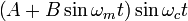 kalau hal ini diuraikan, maka diperoleh
 ![\begin{align} A \sin
\omega_c t + B \sin \omega_m t \sin\ omega_c t
&= A \sin \omega_c t + \frac { B \cos \left( \omega_c - \omega_m
\right) t } { 2 } - \frac { B \cos \left( \omega_c + \omega_m \right) t }
{ 2 } \\ &={\color{blue} A \sin \omega_c t } + {\color{green} \frac
{ B \sin \left[ \left( \omega_c - \omega_m \right) t + \frac{\pi}{2}
\right] }{2}}+{\color{red} \frac{B \sin \left[ \left( \omega_c +
\omega_m \right) t - \frac{\pi}{2} \right] } { 2 } }\end{align}](http://upload.wikimedia.org/math/3/3/9/339fd827df43250f0b707ae8876de11c.png)
 adalah pembawa
  adalah frekuensi samping bawah
  adalah frekuensi samping atas Jika pembawa dimodulasi oleh bentuk
 adalah frekuensi tengah pembawa. Dan
  adalah frekuensi isyarat pemodulasi. Dengan integrasi:
 disebut dengan
  Perbandingan deviasi maksimum dalam


 75 kHz yang memungkinkan frekuensi pemodulasi sebesar 15 kHz.